THIS MANUAL IS FOR FPP v1.x AND IS NOW OUTDATED.
Please follow the link below to go to the current version of the FPP manual.
https://falconchristmas.github.io/FPP_Manual.pdf
The manual is also available by clicking the 'Manual' link at the top of the 'Help' menu in FPP.
Network
The network screen is used to define the network configuration i.e. how the FPP will communicate with controllers, the internet and any other FPP on the network.
There are three or four common network setups that people use for this purpose and for each of these, the required parameters are described below.
For this discussion, a network is referred to as a collection of devices (of which the PI/BBB is the main one) that run on the same subnet i.e. (the same ‘yyy’ component of the IP address xxx.xxx.yyy.xxx).
Tip: If you are using wireless and wired connections, they should both be on separate subnets.
Most home routers will use 192.168.0.x netmask 255.255.255.0, and 192.168.1.x netmask 255.255.255.0 Since 192.168. is being used in both cases (because this is the reserved space for these little LAN networks), the third number is very important in defining a different network between wlan0 and eth0 on our FPP's network settings.
193.192.168.0.x with a netmask of 255.255.255.0, means that the third number in the IP address will define the network, and the x will be the node number
Set the gateway value to be the IP address of the router that is connected to the internet. For any connection that does not have internet access (often eth0), the gateway connection should be blank.
- Set the DNS IP address to be the IP address of the router that is connected to the internet. You can also (less commonly) use Google’s public DNS number 8.8.8.8
Tip: When the FPP boots up, it will announce the IP address that it is using. Alternatively you can use a free utility such as Netscan to identify the IP addresses of devices on the network.
Select the Interface Name to define the required parameters for that interface.
- eth0 – this definition is used for the Ethernet (wired) connection between the FPP, controllers and the router.
- wlan0 - this definition is used for a Wireless (Wifi) connection between the FP and a router.
Note: It is expected if both connections are used, then they will be on separate networks. As an example, the Ethernet (eth0) network will run on 192. 268.3.yyy and the wireless (wlan0) network will run on 192.268.1.yyy.
Interface eth0
This interface must (almost) always be defined.
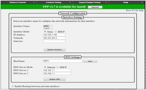
Select the Interface Mode i.e. will the FPP use a static address or a dynamic IP address allocation (DHCP).
By default, the FP will use the DHCP mode and as such will use the IP address that the (hardwired) router allocates to it.
If DHCP has been selected, then the IP address will be populated. If using a Static address mode, then enter the IP address of the PI/BBB.
Note: The IP address must be on the same subnet of the router and the controllers.
Enter 255.255.255.0 as the Netmask
Enter the IP address of the (hardwired) router as the gateway address if that router has access to the internet, else leave the value blank.
Click on ‘Update Interface’ to save the definitions for the interface.
Interface wlan0
This interface need only be defined if the Pi/BBB also has a Wifi connection – see scenario 3 & 4 examples.
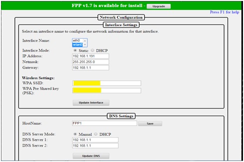
Select the Interface Mode i.e. whether the FPP will use a static address or a dynamic IP address allocation (DHCP).
If DHCP has been selected, then the IP address will be populated. If using a Static address mode, then enter the IP address of the PI/BBB.
Note: The IP address must be on the same subnet of the router that the FPP connects to wirelessly; and as such is expected to be different to the eth0 subnet.
Enter 255.255.255.0 as the Netmask
Enter the IP address of the (wireless) router as the gateway address if that router has access to the internet, else leave the value blank.
Enter the WPA SSID and the PSK of your wireless router. (This has been blanked out in the screen shot example).
Click on ‘Update Interface’ to save the definitions.
DNS Settings
This setting is separate to the eth0 and wlan0 settings.
You can change the default hostname allocated to the FP (FPP1 etc) to one of your liking or leave as allocated.
If the FPP is connected to the internet, then the DNS Server IP addresses is most commonly specified as the IP address of the router with internet access. If not connected to the internet, then ensure that the DNS Server mode is set to Static and the IP address values are blank.
Click on ‘Update Interface’ to save the changes for the interface.
Enable Routing between network interfaces
This option can be used to allow FPP to be used to pass traffic between your wired and wireless networks so you can get to the controller from your home network by going through the Pi.
Example:
192.168.1.nnn is the home network and
192.168.3.nnn is the show network
FPP: 192.168.1.191 – Wifi wlan0 IP address that connects back to home network
FPP: 192.168.3.191 – FPP eth0 address
Controller (i.e. F16V2): 192.168.3.195
Windows, from the command line enter:
route add 192.168.3.0 mask 255.255.255.0 192.168.1.191
Note: You may need to run the CMD as administrator.
OS X:sudo route -n add -net 192.168.3.0/24 192.168.1.191
Then if you enable routing , you should be able to enter the IP address of the controller which is on your show network (192.168.3.195) on your browser and it should take u there directly.
You can replace 'add' with 'delete' in the above.
Network Setup Examples
For the following scenarios:
- The IP address of the internet connected (home network) router is 192.168.1.1. (Subnet 1)
- The IP address of the non internet connected router is 192.168.3.1. (Subnet 3)
Scenario 1 - The FPP is hardwired (via Ethernet) on the home network.
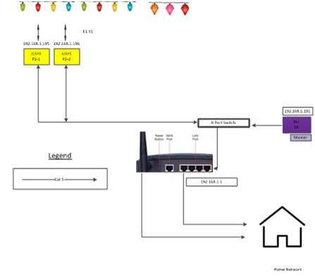
Therefore, only eth0 needs to be defined. All the controllers are on the same home network.
| eth0 | wlan0 | DNS | |
|---|---|---|---|
| Interface name | eth0 | ||
| Interface mode | DHCP/Static | ||
| IP address | 192.168.1.191 | ||
| Network | 255.255.255.0 | ||
| Gateway | 192.168.1.1 | ||
| Host Name | |||
| DNS Server Mode | DHCP | ||
| DNS Server 1 | 192.168.1.1 | ||
| DNS Server 2 | 192.168.1.1 |
Tip: Consider using Unicast only in this configuration to avoid flooding your home network during your show.
Scenario 2 - The FPP is on a separate hardwired Ethernet network (subnet 3) and uses a RAS Clock.
The FP and show network have no access to the internet.
| eth0 | wlan0 | DNS | |
|---|---|---|---|
| Interface name | eth0 | ||
| Interface mode | DHCP/Static | ||
| IP address | 192.168.3.191 | ||
| Network | 255.255.255.0 | ||
| Gateway | |||
| Host Name | |||
| DNS Server Mode | |||
| DNS Server 1 | |||
| DNS Server 2 |
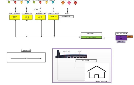
Scenario 3 - The FPP is on a separate Ethernet show network; uses Wifi for internet.
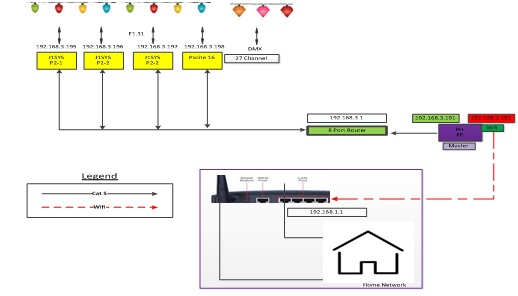
| eth0 | wlan0 | DNS | |
|---|---|---|---|
| Interface name | eth0 | wlan0 | |
| Interface mode | DHCP/Static | DHCP/Static | |
| IP address | 192.168.3.191 | 192.168.1.191 | |
| Network | 255.255.255.0 | 255.255.255.0 | |
| Gateway | 192.168.1.1 | ||
| Host Name | |||
| DNS Server Mode | DHCP | ||
| DNS Server 1 | 192.168.1.1 | ||
| DNS Server 2 | 192.168.1.1 |
Scenario 4 - Two FPPs are on a separate Ethernet network; both use Wifi for internet.
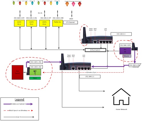
In this example FP1 (FPP1) runs on the Raspberry PI as a master and FP2 (FPPBB) runs on a BBB as a Remote slave.
| PI- FP1 | BBB -FP2 | |||||
|---|---|---|---|---|---|---|
| eth0 | wlan0 | DNS | eth0 | wlan0 | DNS | |
| Interface name | eth0 | wlan0 | eth0 | wlan0 | ||
| Interface mode | DHCP/Static | DHCP/Static | DHCP/Static | DHCP/Static | ||
| IP address | 192.168.3.191 | 192.168.1.191 | 192.168.3.192 | 192.168.1.192 | ||
| Network | 255.255.255.0 | 255.255.255.0 | 255.255.255.0 | 255.255.255.0 | ||
| Gateway | 192.168.1.1 | 192.168.1.1 | ||||
| Host Name | FPP1 | FPP1 | FPPBB | FPPBB | ||
| DNS Server Mode | DHCP | DHCP | ||||
| DNS Server 1 | 192.168.1.1 | 192.168.1.1 | ||||
| DNS Server 2 | 192.168.1.1 | 192.168.1.1 |
Note: The hostname is optional. The FPP will allocate a different hostname as required if one is not specified.