THIS MANUAL IS FOR FPP v1.x AND IS NOW OUTDATED.
Please follow the link below to go to the current version of the FPP manual.
https://falconchristmas.github.io/FPP_Manual.pdf
The manual is also available by clicking the 'Manual' link at the top of the 'Help' menu in FPP.
Channel Outputs
This section is used to define how your channels map to universes in your controllers and which controller types are being used for different outputs. These can be E131, DMX, P10 Panels via an Octoscroller , Ws28xx pixels connected via a cape etc.
Note: If the FPP is the PI version, then the following tabs are available:
There is no BBB definition tab. If instead, it is the BBB version, then the following tabs are available:

Note: The BBB/BBG version of the FPP has an additional tab ‘BBB’ to support controller cape definitions that are specific to the BBB/BBG including setting up the Octoscroller definitions for the P10 panel configuration. It won’t have the Falcon Pixelnet/DMX tab.
E1.31
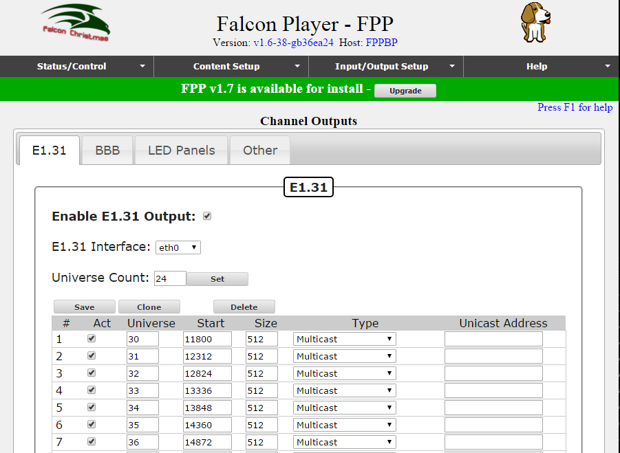
This screen is used to define and map the channels of ‘models’ in your sequences to Universes. It is also use to define whether the FPP should use Unicast or Multicast. The Universes defined against each channel range must align with the Universes that the controller(s) are expecting and also align with the number of channels or nodes defined on each output of the controller. See examples at the end of this section.
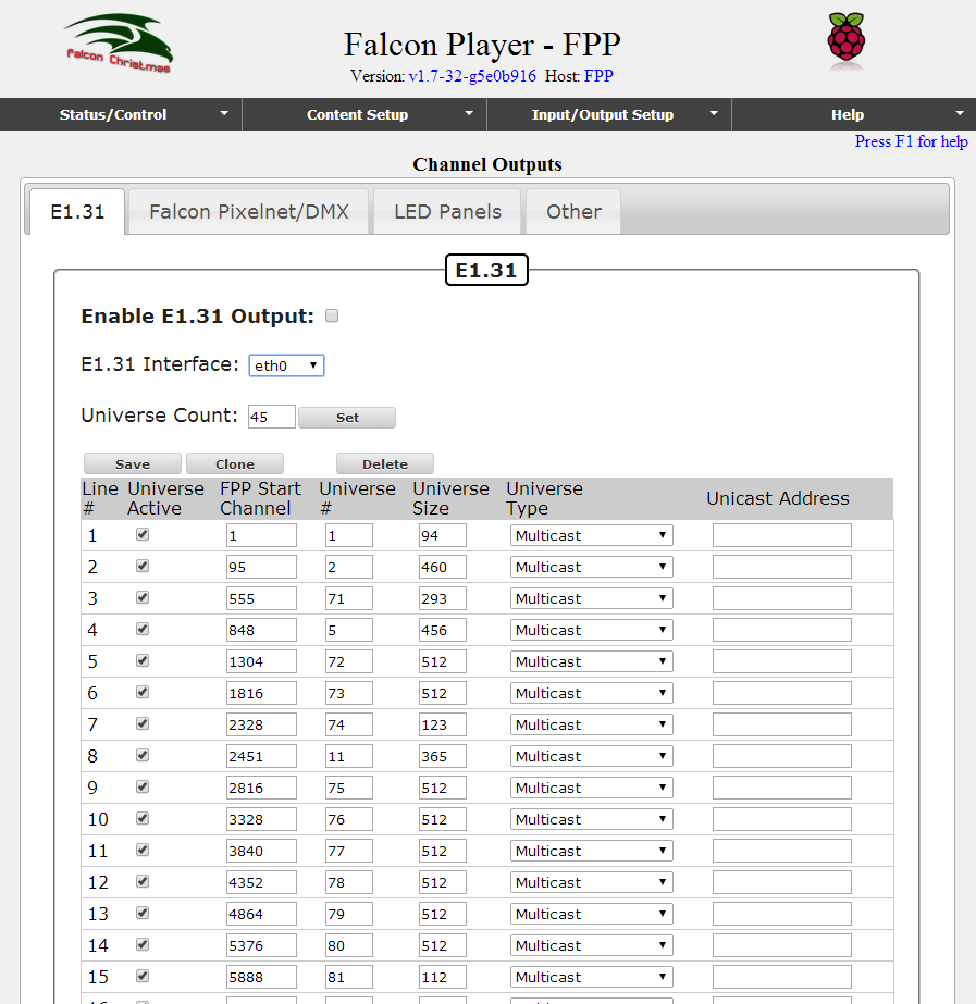
- The ‘Enable E1.31 Output’ must be ticked if the definitions pertain to channels and universes on the PI.
- Select ‘eth0’ as the E1.131 interface as normally you will be using the ethernet connection from the PI/BBB to your controllers.
- Specify how many lines of Universe definitions you plan to have and Click on the Set button. Accordingly, those many rows will be created in the list. You can always expand this later.
For each row, specify the Universe number, the start channel number and the number of channels (size). Specify Unicast or Multicast.
If Unicast is specified, then the IP address of the controller serving that universe must be specified.
Note: The controller IP address must be on the same subnet as the FPP.
If Multicast is specified, then the IP address is not required as the data will be broadcast to all controllers on the network (i.e. on the same subnet) as the FPP.
Click on Save, to save the definitions entered.
- To clone a row of definition, highlight the row and click on the Clone button. A window will pop up where you can define how many rows are to be added to the definition. After which, go to the rows that have been added and update the details in the row.
- To delete a definition, highlight the row and Click on the Delete button.
- Ensure that the Activate attribute is ticked for each active definition. By unticking the ‘Act’ attribute, the definition will be ’retained’ but will not be used.
Example 1
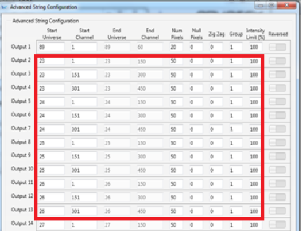
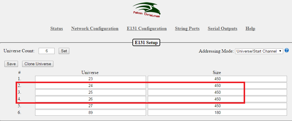
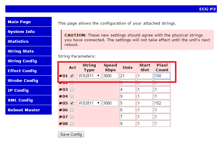
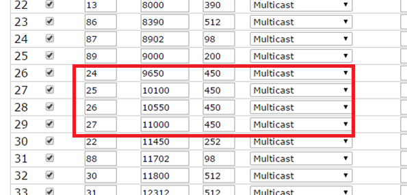
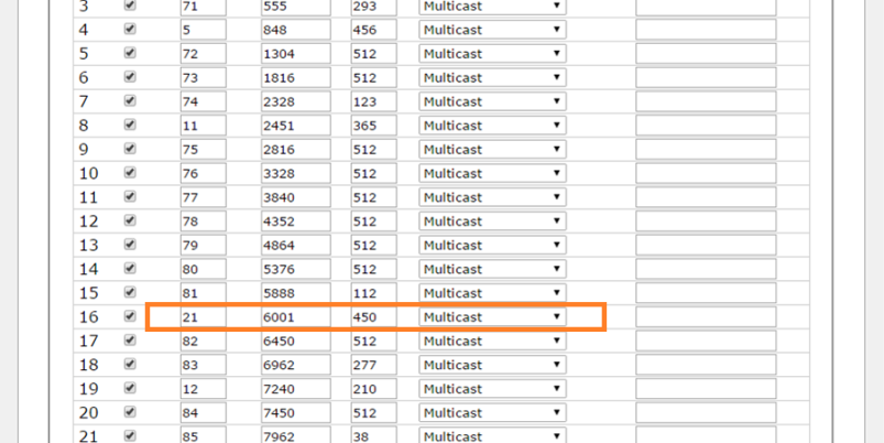
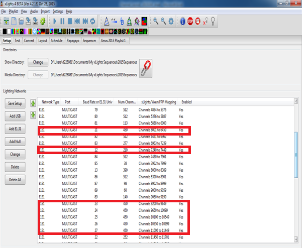
The following setup example shows an FPP on a PI driving a Pixlite16 with Universes (24-26) , a J1sys P2 using Universe (21) , the FPP configuration to support it and the xLights setup definition (which is not required, but included for context).
The Pixlite16 configuration has been duplicated on an F16V2 (as a test only) and has been included for reference.
Pixlite16 definition (snapshot)
F16V2 definition (snapshot)

J1SYSP2
FPP1
xLights
Example 2
The following setup example shows an FPP on a BBB driving P10 Panels. Refer to the LED section to view the panel definition details.
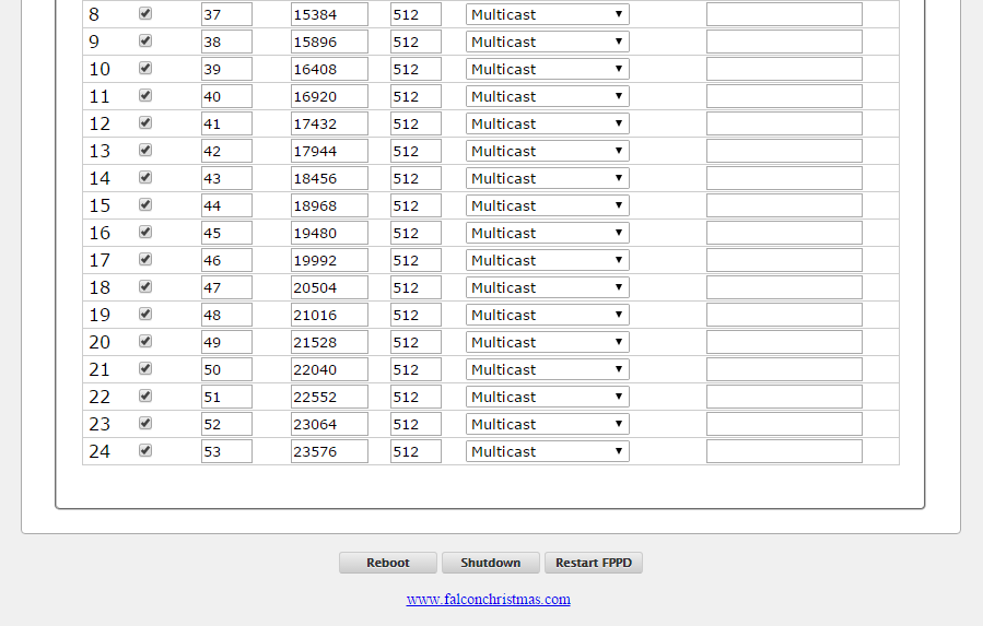
Pixelnet/DMX
To be done by someone who knows this area.
The FPD output can send 32,768 channels out 12 ports configured for the DMX or Pixelnet protocols. This is currently limited to the first 32768 channels in a sequence.
LED Panels
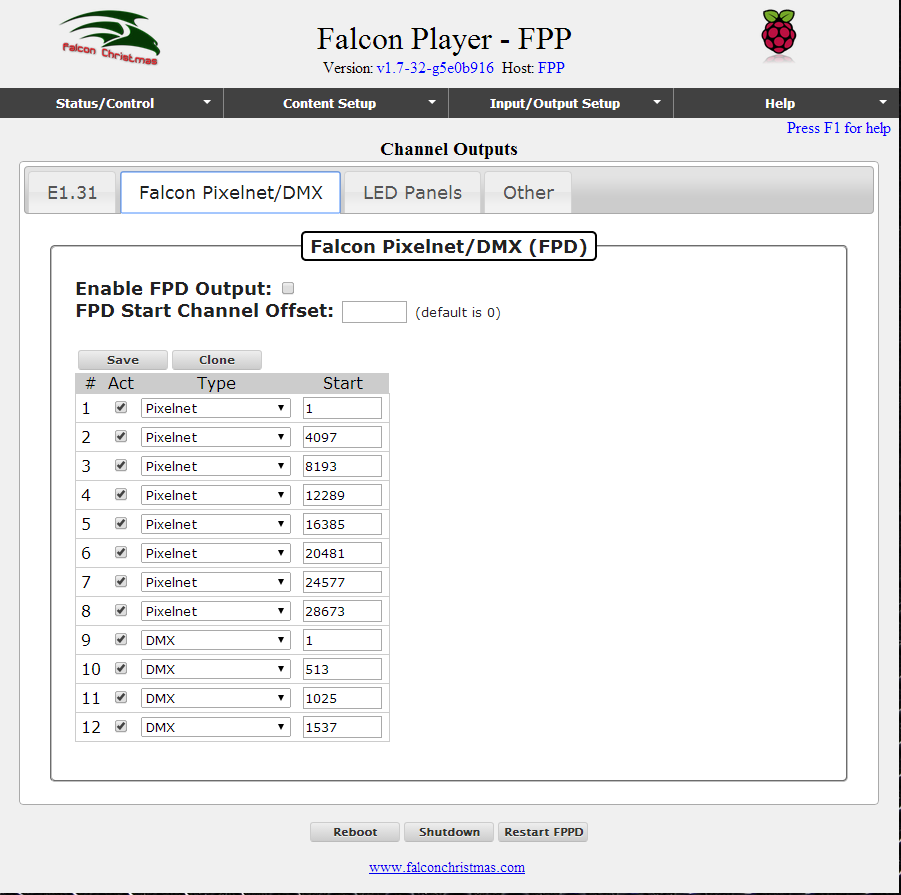
This screen is used to define the configuration of one or more P10 panels connected to an Octoscroller over a BBB/BBG.
- Ensure that the Enable P10 Panel Output attribute is selected.
- Define the panel layout i.e. number of panels wide and high and the panel size (the most common being 32 pixels wide and 16 pixels tall).
The setup in this example consists of 8 P10 panels (4H x 2 W) driven via a Beagle Black Bone (BBB) with an octoscroller running the Falcon Player.
- The Start Channel specified should align with the start channel in the sequencer ‘model definition’ and the model Start Corner must also align with the model definition.
Note: For context, in xLights, the model used is defined as a model ‘P10Matrix’ which is a horizontal matrix with 64 strings (corresponds to number of rows), # of RGB nodes per string as 64 (corresponds to the columns) and # of strands per string = 1. The starting corner must be set to Top Left irrespective of how you configure your panels on the BBB. The start channel in the model is 11800 and From Output is set to 1.
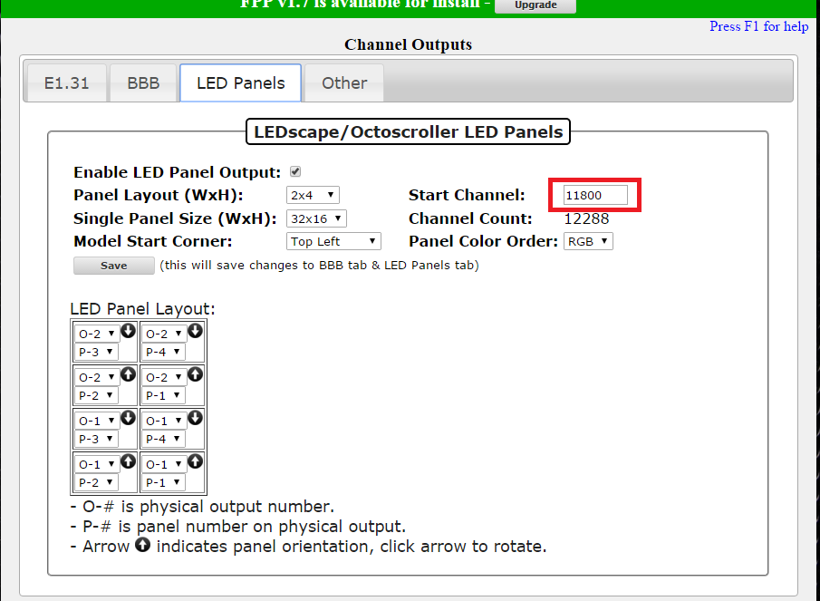
LED panel Layout
The LED panel layout component of the string is used to define:
- The layout of the panels with respect to each other
- The (data ribbon) connection from the Octoscroller to the panels
The LED Panel layout will default to the required number of panels based on the value specified in the ‘LED Panel Layout’ attribute.
Clicking on the Arrow will rotate the panel orientation.
‘O’ refers to the physical connection from the Octoscroller to the panel.
‘P’ refers to the panel to panel daisy chain position within the connection
In the example above there are two outputs from the Octoscroller, each driving 4 panels.
Each panel has two white arrows on the back. One is vertical and one is horizontal.
All definitions on the BBB are based on you standing in front of the panels (i.e. your back is to the street) and you are then looking at the front of the panels. Imagine that the panels are see-through and looking at the panels from the front, you can see the arrows.
The panels are in landscape mode and 4H * 2 wide
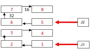
From the octoscroller,
- The cable from J1 goes to panel 1 above, which is connected to 2 and then to 3 and then to 4.
- The cable from J2 goes to panel 5 above, which is connected to 6 and then to 7 and then to 8
- Panels 1 and 2 have their vertical arrows pointed UP
- Panels 3 and 4 have their vertical arrows pointed DOWN (i.e. they are upside down as compared to panels 1 & 2)
- Panels 5 and 6 have their vertical arrows pointed UP
- Panels 7 and 8 have their vertical arrows pointed DOWN (i.e. they are upside down as compared to panels 5 & 6)
Note: Other possibilities that could have been used are, one output to drive all 8 panels or 4 outputs, each driving one row of 2 panels each.
- On the E1.31 page, the Enable E1.31 should not be ticked and no E1.31 channel definition is required as E1.31 is not used to drive the panels – the output is memory mapped.
- On the BeagleBone Black String cape page, the Enable BBB String cape should not be ticked and no string output definition is required.
Note: If you wish to use Bridge Mode (i.e. play the sequence directly from the sequencer to test), then you need to define universes on the E1.31 tab.
BBB
This screen is to be used if you are using one of the BBB string capes (other than the Octoscroller).
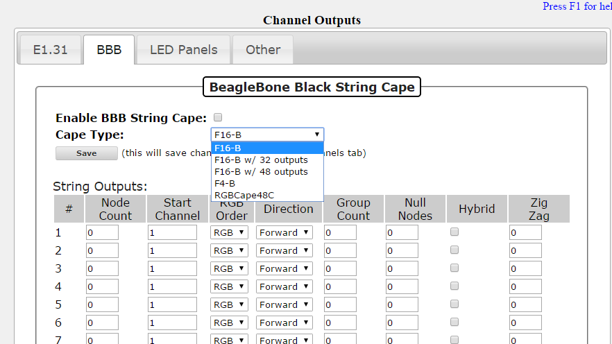
Select the cape type. The string outputs will accordingly change based on the cape selected. Enter the configuration details, select ‘Enable BBB String Cape’ and click on Save to save the definition.