THIS MANUAL IS FOR FPP v1.x AND IS NOW OUTDATED.
Please follow the link below to go to the current version of the FPP manual.
https://falconchristmas.github.io/FPP_Manual.pdf
The manual is also available by clicking the 'Manual' link at the top of the 'Help' menu in FPP.
Other
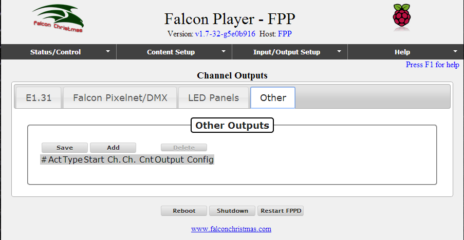
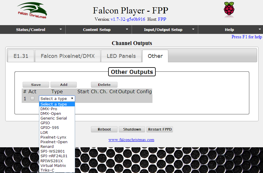
This screen is used to add definitions for output controller types that are somewhat specialized or where strings/strips are connected directly to the GPIO outputs.


DMX Open - The DMX Open output can send DMX data out generic FTDI-based USB to RS485 dongles. Other RS485 dongles may work if they support setting arbitrary bit rates. Support should include the following dongles: Entec Open DMX, LOR, and D-Light along with generic FTDI-based USB to RS485 adapters.
DMX Pro - The DMX Pro output can send DMX data out Entec-Pro compatible dongles. This should include the following dongles: Entec-Pro, Lynx USB dongle w/ DMX firmware, DIYC RPM, DMXking.com, and DIYblinky.com. If the dongle works using xLights DMX Pro output, it should work in the Falcon Player.
RGBMatrix - The RGBMatrix output can drive up to four of the 'P10' style 32x16 RGB LED Panels. These panels may be wired directly to the Pi's GPIO header or an adapter board may be used to handle the wiring. The adapter board PCB info and BOM are listed in the Falcon wiki at RGB-LED_Adapter. Make sure the pinout of your LED panels matches the pinout of the LED port on the adapter board before using one of these with your panel or it will not function properly.
RGBMatrix Output Connections
| LED Panel | Raspberry Pi |
|---|---|
| GND - Ground | Pin 3 - GND |
| R1 - Red 1st bank | Pin 11 - GPIO 17 |
| G1 - Green 1st bank | Pin 12 - GPIO 18 |
| B1 - Blue 1st bank | Pin 15 - GPIO 22 |
| R2 - Red 2nd bank | Pin 16 - GPIO 23 |
| G2 - Green 2nd bank | Pin 18 - GPIO 24 |
| B2 - Blue 2nd bank | Pin 22 - GPIO 25 |
| A - Row address | Pin 26 - GPIO 7 |
| B - Row address | Pin 24 - GPIO 8 |
| C - Row address | Pin 21 - GPIO 9 |
| D - Row address | (Not Used for 32x16 panels |
| OE - Neg. Output Enable | Pin 3 - GPIO 2 |
| CLK - Serial Clock | Pin 5 - GPIO 3 |
| STR - Strobe row data | Pin 7 - GPIO 4 |
Pixelnet Open - The Pixelnet Open output can send Pixelnet data (one 4096-channel universe) out generic FTDI-based USB to RS485 dongles.
Pixelnet Lynx - The Pixelnet Lynx output can send Pixelnet data (one 4096-channel universe) out the Lynx USB dongle w/ Pixelnet firmware.
Renard - The Renard output can drive up to 4584 channels at the highest speeds using standard USB to serial dongles.
SPI-WS2801 - The SPI-WS2801 output can drive one string of WS2801 pixels directly off the Raspberry Pi's SPI port. The data, clock, and ground lines attach directly to the Pi while power for the pixels is injected from another source.
SPI-WS2801 Output Connections
| WS2801 Function | Raspberry Pi |
|---|---|
| Clock | Pin 23 - SCLK |
| Data | Pin 19 - MOSI |
| Ground | Pin 25 - GND |
| Pixel Power | Not Connected to Pi |
RPIWS281X - The RPIWS281X output can drive two independent strings of WS281x pixels directly off the Raspberry Pi's GPIO ports. The data and ground lines attach directly to the Pi while power for the pixels is injected from another source.
RPIWS281x Output Connections
| WS281x Function | Raspberry Pi |
|---|---|
| Data String #1 | Pin 12 - GPIO18 |
| Data String #2 | Pin 35 - GPIO19 (Only on A+/B+/B v2) |
| Ground | Pin 25 - GND |
| Pixel Power | Not Connected to Pi |
Note: This channel output is not supported on the Pi v2 B (only) in FPP v1.7.
Triks-C - The Triks-C output can drive up to four LEDTriks modules attached to Triks-C or Pix-C boards. The start channel is specified along with the serial port the Triks-C is connected to and the panel layout. Panels may be laid out in a horizontal row of 1-4 panels, a vertical column of 1-4 panels, or a 2x2 grid. Panels must be numbered starting at the top left, going across then down. In a 2x2 layout, the top row would be panels 1 and 2 and the bottom row would be panels 3 and 4 with panel 3 below panel 1 and panel 4 below panel 2.
GPIO - The GPIO output can drive a single GPIO pin high or low based on a channel's value being zero (low) or non-zero (high). This may be used to drive output relays or trigger other attached devices.
GPIO Pins available on the Pi model B and B+
| Name | BCM Pin # | Model B | Model B+ |
|---|---|---|---|
| GPIO0 | 17 | P1 - Pin 11 | J8 - Pin 11 |
| GPIO1 | 18 | P1 - Pin 12 | J8 - Pin 12 |
| GPIO2 | 27 | P1 - Pin 13 | J8 - Pin 13 |
| GPIO3 | 22 | P1 - Pin 15 | J8 - Pin 15 |
| GPIO4 | 23 | P1 - Pin 16 | J8 - Pin 16 |
| GPIO5 | 24 | P1 - Pin 18 | J8 - Pin 18 |
| GPIO6 | 25 | P1 - Pin 22 | J8 - Pin 22 |
| GPIO7 | 4 | P1 - Pin 7 | J8 - Pin 7 |
| GPIO8 | 28 | P5 - Pin 3 | N/A |
| GPIO9 | 29 | P5 - Pin 4 | N/A |
| GPIO10 | 30 | P5 - Pin 5 | N/A |
| GPIO11 | 31 | P5 - Pin 6 | N/A |
| GPIO21 | 5 | N/A | J8 - Pin 29 |
| GPIO22 | 6 | N/A | J8 - Pin 31 |
| GPIO23 | 13 | N/A | J8 - Pin 33 |
| GPIO24 | 19 | N/A | J8 - Pin 35 |
| GPIO25 | 26 | N/A | J8 - Pin 37 |
| GPIO26 | 12 | N/A | J8 - Pin 32 |
| GPIO27 | 16 | N/A | J8 - Pin 36 |
| GPIO28 | 20 | N/A | J8 - Pin 38 |
| GPIO29 | 21 | N/A | J8 - Pin 40 |
GPIO Outputs on the PiFace
| Name | Pin # |
|---|---|
| Output 1 | 200 |
| Output 2 | 201 |
| Output 3 | 202 |
| Output 4 | 203 |
| Output 5 | 204 |
| Output 6 | 205 |
| Output 7 | 206 |
| Output 8 | 207 |
GPIO-595 - The GPIO-595 output can drive up to 16 daisy-chained 74HC595 Shift Register IC's using a set of 3 GPIO Output pins. See the table below for connection information. Pick one set of outputs 'GPIO 17-18-27' or 'GPIO 22-23-24', do not connect the 74HC595 to both sets of GPIO Pins.
GPIO-595 Output Connections
| Function | 74HC595Pin # | GPIO 17-18-27 | GPIO 22-23-24 | ||
|---|---|---|---|---|---|
| BCM GPIO | Pin # | BCM GPIO | Pin # | ||
| Clock | 11 - SRCLK | BCM 17 | P1 - Pin 11 | BCM 22 | P1 - Pin 15 |
| Data | 14 - SER | BCM 18 | P1 - Pin 12 | BCM 23 | P1 - Pin 16 |
| Latch | 12 - RCLK | BCM 27 | P1 - Pin 13 | BCM 24 | P1 - Pin 18 |
As an example, for Lynx USB dongles, add a new entry for each dongle.
For a ‘Lynx USB Dongle – Flash for DMX’, select ‘DMX-Pro’ as the Type attribute.
For a ‘Lynx USB Dongle – Flash for Pixelnet’, select ‘Pixelnet-Lynx’.
Set the absolute start channel for each and click on Save. Restart the fppd.
Tip: If your DMX universe overlaps your Pixelnet universe, you can use a start channel of '1' for each, but if they don't overlap, then you'll set something like '1' for DMX and '513' for Pixelnet or '1' for Pixelnet and '4097' for DMX depending on how your channels are ordered in your sequencer.
Virtual Matrix
The ‘Virtual Matrix’ type definition is used to support using the HDMI output of the PI as a virtual matrix to project effects to an HDMI monitor or projector. This is further described in the section Virtual Matrix.